

From Downhole Diagnostics to Predictive Strategy: A Comprehensive Handbook for Petroleum Engineers and Field Operators.
In the artificial lift sector, the Sucker Rod Pump (SRP) remains the dominant technology due to its reliability and flexibility. However, operational inefficiency and premature failure continue to cost the industry billions annually in workover expenses (OpEx) and deferred production.
As we navigate through 2025, the maintenance of these pumps has evolved from a reactive "run-to-failure" model to a proactive, data-driven discipline. This comprehensive guide details the technical nuances of maintaining oil rod pumps, combining legacy field experience with modern API standards and digital monitoring technologies.
Chapter 1: The Pre-Installation Phase – Where Longevity Begins
Many pump failures are predetermined before the pump even enters the wellbore. Proper storage, handling, and preparation are the foundational steps of maintenance.
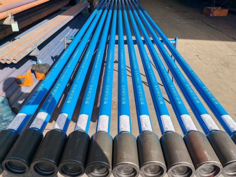
1.1 Storage and Handling Protocols
An API 11AX pump is a precision instrument with clearances often less than 0.003 inches. Improper handling destroys this precision.
Horizontal Support: Pumps must always be stored and transported horizontally. They should be supported at intervals of no more than 3 to 5 feet to prevent barrel sagging. A sagged barrel will cause immediate plunger seizure.
Protective Caps: Thread protectors and shipping caps must remain in place until the moment of installation. This prevents dust, grit, and moisture from entering the barrel.
Corrosion Preservation: If a pump is stored for more than 30 days, it must be filled with a rust-inhibiting oil. The shop environment should be climate-controlled to prevent condensation rust on polished internal surfaces.
1.2 Pre-Running Checks
Before the pump is picked up by the rig blocks, a final field inspection is mandatory:
Visually Inspect Threads: Check for any dings or debris on the threads. Use a thread profile gauge if damage is suspected.
Verify Plunger Fit: For manually assembled pumps, verify the plunger moves freely within the barrel. Any resistance ("tight spots") on the surface translates to catastrophic failure downhole under thermal expansion.
Record Data: Log the pump’s serial number, metallurgy (e.g., Spray Metal vs. Chrome), and clearance fit into the well file system.
Chapter 2: The Critical Start-Up Procedure (The First 24 Hours)
Field statistics show that a significant percentage of pumps fail within the first week due to improper start-up procedures. This is often referred to as "infant mortality."
2.1 The "Burn-In" Phenomenon
New plungers and barrels have microscopic surface peaks (asperities). If run too fast immediately, these peaks shear off, generating intense localized heat—often exceeding 500°F (260°C)—which causes the metal to expand and seize.
2.2 The Soft-Start Protocol
To prevent burn-in, follow this rigorous start-up sequence:
Prime the Tubing: Never start a pump dry. Fill the tubing string with fluid (oil or compatible water) to lubricate the barrel and verify the standing valve holds pressure.
Initial Operation (0-2 Hours): Operate the pumping unit at the slowest possible speed (e.g., 3-4 Strokes Per Minute). This allows the plunger to polish the barrel wall and establish a hydrodynamic fluid film.
Ramp-Up (2-24 Hours): Gradually increase the speed to the target SPM over a 24-hour period.
Monitor Temperature: If the polished rod feels hot to the touch, the downhole pump is likely overheating. Stop immediately and allow it to cool.
Chapter 3: Operational Maintenance – The Art of Downhole Monitoring
Once the pump is at depth, "maintenance" shifts from physical care to data analysis. In 2025, the Dynamometer Card is the primary tool for health assessment.
3.1 Interpreting Dynamometer Cards
A dyno card plots Load (lbs) vs. Position (inches). It is the X-ray of the pump.
The Ideal Card: A full rectangular shape indicates the pump is filling completely with liquid and valves are holding tight.
Fluid Pound (The Destroyer):
Symptoms: The card shows a sharp, vertical drop on the downstroke at a specific position.
Physics: The barrel is only partially full. The plunger hits the fluid interface at high velocity, sending a shockwave up the rod string.
Consequence: This shockwave buckles rods, shatters valve balls, and unscrews tubing connections.
Action: Reduce pumping speed or set the Pump-Off Controller (POC) to shut down sooner.
Gas Lock:
Symptoms: The card looks like a flat, narrow loop or a "club." The lines of compression and expansion overlap.
Physics: Gas is trapped between the traveling and standing valves. Being compressible, the gas expands and contracts without allowing the valves to open.
Action: Increase tubing backpressure to force gas into solution, or verify the gas anchor/separator design.
3.2 Managing Stroke Geometry
Long and Slow Strategy:
Engineering principles dictate that running a long stroke length at a slow speed is superior to a short stroke at high speed.
Benefit 1: Fewer cycles per day mean fewer stress reversals on the rods (Fatigue Life).
Benefit 2: Better compression ratio helps mitigate gas locking issues.
Benefit 3: Slower plunger velocity reduces fluid friction and erosion wear.
Chapter 4: Chemical Maintenance – The Invisible Shield
The produced fluid is often a toxic cocktail of corrosives and abrasives. Mechanical strength alone cannot survive this; chemical engineering is required.
4.1 Corrosion Management
The Threats:
Sweet Corrosion (CO₂): Causes deep, sharp pitting on steel surfaces.
Sour Corrosion (H₂S): Causes hydrogen embrittlement and sulfide stress cracking.
The Maintenance Strategy:
Filming Amines: Use corrosion inhibitors that create a molecular film on the metal.
Application Method: For severe wells, continuous injection via a capillary tube or backside flush is required. "Batch treating" (dumping a drum once a week) leaves the pump unprotected for days at a time.
4.2 Scale and Solids Control
Scale (Calcium Carbonate/Sulfate): Scale builds up like concrete, locking the plunger or clogging the intake.
Action: Scale inhibitors prevent crystal growth. In extreme cases, acid jobs are required to dissolve existing scale.
Solids (Sand/Fines):
Action: If a well produces sand, use a dispersant to keep solids suspended in the oil.
Crucial Rule: Avoid shutting down sand-producing wells. When flow stops, sand settles out of the tubing and piles up on top of the pump, causing it to stick ("sanded in") when you try to restart.
Chapter 5: Surface Unit Maintenance – Impact on Downhole Life
The pumping unit (Pumpjack) acts as the driver. If the driver is erratic, the passenger (the rod pump) suffers.
5.1 Alignment is Everything
The most common cause of one-sided barrel wear is surface misalignment.
The Carrier Bar Test: Stop the unit at the middle of the stroke. The polished rod should hang perfectly centered in the stuffing box and the carrier bar. If it "rubs" one side, the unit must be physically moved or shimmed.
Consequence: A misalignment of just 1 degree can cause thousands of pounds of side-loading force on the downhole pump, wearing through the barrel wall in weeks.
5.2 Stuffing Box Maintenance
Lubrication: A dry stuffing box creates friction heat that can damage the polished rod. Modern units use auto-lubricators.
Leak Management: Do not over-tighten the packing gland to stop a leak. Over-tightening acts as a brake on the rod, increasing load and wear. If it leaks, replace the packing rubbers (cones).
5.3 Counterbalance
Proper Balancing: An unbalanced unit causes uneven rotation speed (whipping). This creates peak torque spikes that send harmonic vibrations down the rod string, damaging the pump connection threads.
Check: Monitor the amperage draw on the upstroke vs. downstroke. They should be roughly equal.
Chapter 6: Advanced Troubleshooting & Failure Analysis
True maintenance happens after a failure. This is called Root Cause Analysis (RCA). Don't waste a failure—learn from it.
6.1 Analyzing the Plunger
Uniform Wear: Normal aging.
Vertical Scratches (Grooves): Abrasion from sand or scale. Solution: Upgrade to Hard-Lined Barrels or Spray Metal Plungers; improve downhole sand control.
Pitting/Rust: Corrosion failure. Solution: Check inhibitor pump performance; upgrade metallurgy to Stainless Steel, Monel, or Brass.
Galling/Seizing: Thermal runaway or poor lubrication. Solution: Check fluid levels; ensure proper start-up procedures; check for pump-off conditions.
6.2 Analyzing the Valves (Balls and Seats)
Washed Out (Channels cut in the seat): Fluid cutting due to leakage. Solution: This often starts as a small leak. Improve QC on new valves and check for impact damage.
Shattered Ball: Impact damage from "Fluid Pound." Solution: This is operational. Install a POC or slow the unit down.
Material Selection:
Standard: Stainless Steel.
Abrasive: Cobalt or Tungsten Carbide.
Corrosive & Abrasive: Silicon Nitride (Ceramic) balls are becoming the 2025 standard for extreme durability.
Chapter 7: The Digital Transformation
In 2025, maintenance is no longer just manual; it is digital.
7.1 Real-Time Pump Off Controllers (POC)
Modern POCs are edge-computing devices. They don't just stop the pump; they learn.
Adaptive Algorithms: The POC analyzes the last 100 strokes to determine the optimal fillage set-point, adjusting automatically to changing reservoir inflow.
Remote Control: Operators can adjust stroke speeds and start/stop parameters from a smartphone, eliminating unnecessary trips to the wellsite.
7.2 Predictive Maintenance
Using IoT sensors on vibration and load:
Trend Analysis: AI software can detect a slow degradation in valve efficiency weeks before it becomes critical, allowing operators to schedule a "cheap" pump change proactively rather than a strictly "reactive" emergency workover.
Chapter 8: Safety and Environmental Protocols (HSE)
Maintenance cannot come at the cost of safety. Rod pumping systems involve high voltage, high pressure, and heavy moving masses.
8.1 Energy Isolation (LOTO)
Mechanical Energy: The counterweights have huge potential energy. Always chain the brake and secure the weights before approaching the unit.
Electrical Energy: Lock Out / Tag Out (LOTO) the main panel.
Pressure Energy: Bleed off tubing and casing pressure before opening any valve or stuffing box.
8.2 H₂S Awareness
In sour fields, opening a pump for inspection can release trapped pockets of Hydrogen Sulfide gas. Personal H₂S monitors are mandatory.
Chapter 9: Economic Implications and ROI
Maintenance is an investment, not just a cost.
Cost of Failure: A typical workover (rig time, crew, new pump) can cost $10,000 to $50,000, not including lost production.
ROI Calculation: Investing $2,000/year in chemicals and $500 in proper monitoring that extends pump life from 6 months to 18 months yields a Return on Investment (ROI) of over 300%.
The Bottom Line: The cheapest pump is not the one with the lowest price tag; it is the one with the longest run-life.
Conclusion
The service life of an oil rod pump is a reflection of the operational discipline of the field team. By adhering to the "Three Pillars of Maintenance"—Precision Installation, Chemical Protection, and Data-Driven Operation—operators can transform their artificial lift systems from a liability into a reliable asset.
As we embrace the technologies of 2025, the combination of robust API hardware and intelligent software monitoring provides the ultimate path to efficiency. Treat your pump like the precision instrument it is, and it will reward you with years of trouble-free production.