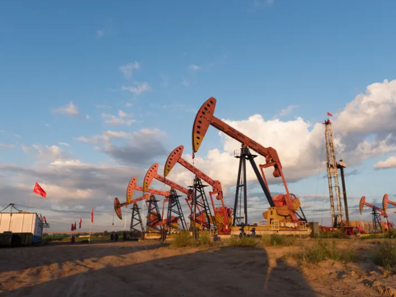
With the continuous extension of oil well development time and the increase in oilfield production projects, coupled with the high complexity of the oil reservoir environment and the year-round operation of oil wells, the types of oil well failures have become more complex. The following section uses the surface engineering of oil wells as an example to analyze common oil well failures and corresponding countermeasures.
In the oil extraction industry, the pumping unit plays a crucial role. However, the downhole working environment and complex operating conditions frequently lead to various failures in the pumping unit. Furthermore, the scattered distribution of oil wells and the inconvenience of roads between them result in high management and maintenance costs. Therefore, the construction of a fast, efficient, and streamlined fault classification model and visualization terminal is particularly important.
1. Judgment of Oil Well Failure Causes:
1.1 Dynamogram Method: The operating principle is: using an oil well fluid level dynamogram comprehensive testing instrument, after the pumping unit completes one stroke, the change in the load on the suspension cable is recorded, resulting in a closed curve. The area of the closed figure formed by the curves represents the actual "work" done by the pump during one stroke of the polished rod, thus determining the pump's operating status within the wellbore. Common dynamometer diagrams include those indicating tubing leakage, oil viscosity, insufficient fluid supply, pump jamming, pump collision, pump failure, leakage of fixed and traveling valves, rod breakage, and gas interference. When using this method, relevant personnel must analyze daily well management records, such as water cut change records, well production reports, and casing pressure records, to achieve a comprehensive judgment. This method is applicable to judging various causes of well failures and has a very high accuracy rate, providing a reliable basis for developing reasonable and accurate repair plans after identifying the cause of well failures.
1.2 Wellhead Pressure Retention Method: The operating principle is as follows: During normal operation of the pumping unit, the back pressure gate is closed, and then the change in tubing pressure is observed through a 2.5MPa pressure gauge. Based on the pressure rise and fall, the cause of the pump failure is determined and analyzed. For example, if the pressure rises during the upstroke of the pumping unit and remains relatively stable or slightly decreases during the downstroke, this indicates that the pump is operating normally. If the pressure initially increases slowly during the upstroke, and then stops rising after about five minutes, or if the pressure drops significantly, this indicates a problem with the pump valve seat seal, suggesting a pump leak. Additionally, if the pressure gauge remains relatively stable during both the upstroke and downstroke, with a slight decrease during the upstroke, this suggests a possible sucker rod breakage in the well. In this case, relevant personnel should verify this information in conjunction with other data. This method is commonly used to check whether the pump valves are functioning properly and to diagnose faults in normal operation. However, if the tubing in the well is severely waxed, this method may lead to inaccurate results. Therefore, the wellhead pressure test has certain limitations in routine fault diagnosis.
1.3 Pump Testing Method: The operating principle is as follows: During field operations, liquid is injected into the tubing using a cement pump truck. The pump pressure and wellhead pressure are compared to determine if the pump is malfunctioning. One method is to place the piston in the working cylinder for pressure testing. After stopping the pump, liquid is injected into the tubing. If the wellhead pressure drops or there is no pressure, it indicates significant leakage in both the fixed and traveling valves. If the wellhead pressure rises, the traveling valve is in good condition. If the wellhead pressure and casing pressure rise together, it indicates tubing leakage. Another method is to remove the piston from the working cylinder and test the pump by pumping liquid. If the pressure drops or there is no pressure at all, it indicates leakage in the fixed valve. This method is mainly applicable to determining whether there is leakage in the tubing of an oil well, whether the components of the pump are working properly, and the cause of malfunctions during normal operation.
1.4 Tubing Damage: Damage to the tubing itself can also cause leakage. One cause is defects in the tubing manufacturing process. For oil tubing, the national standard adopted is the American Petroleum Institute (API) SPEC 5CT standard, which has clear requirements for the composition, hardness, and strength of the tubing. However, due to differences in manufacturing processes among enterprises, the quality of the tubing materials varies, making them prone to leakage during oil and gas extraction due to inherent defects. Secondly, environmental factors can damage the tubing. During use, well inclination and other well structure factors can cause uneven wear between the tubing and the inner wall of the casing, leading to cracks or perforations and leakage. Furthermore, the oil and gas transported by the tubing, as well as formation sand production, also cause corrosion and damage, especially when the tubing type is mismatched with the application environment, easily leading to corrosion perforation and leakage.

2. Troubleshooting Measures:
2.1 Troubleshooting Measures for Wax Sticking in Oil Pumps: There are many ways to deal with wax sticking in oil wells, a common method being the "pump-touching method." The specific procedure is as follows: First, stop the pumping unit at 30-40cm below the bottom dead center, turn off the power, tighten the brake, and secure it above the blowout preventer (BOP) box using the square clamp. Start the pumping unit to separate the suspension cable from the square clamp on the polished rod. Then, turn off the power again and tighten the brake to transfer the load from the pumping unit. Mark the position of the clamp above the suspension cable. Next, loosen the square clamp above the suspension cable and slowly release the brake. After the upward suspension cable and the marked position exceed the original anti-blowout distance, tighten the brake and re-clamp the clamp above the suspension cable to allow the pumping unit to bear the load. Remove the square clamp above the BOP box, release the brake, and start the pumping unit. After approximately four pump impacts, restore the original anti-blowout distance and start the pumping unit for production. If the blockage is successfully cleared and production is normal, add an appropriate amount of dewaxing agent to the wellbore through the casing pressure valve, depending on the actual wax buildup in the well. If the pumping unit is severely blocked by wax, the boiler pump truck should periodically perform hot backwashing operations on the well, or the work team should be required to perform regular pump inspections. During pump inspection, the sucker tubing and sucker rod must undergo surface dewaxing and hot-scalding cleaning.
2.2 Handling Measures for Sand Stuck in Oil Wells: The main cause of sand stuck in oil wells is that during oil production, oil layer sand particles enter the casing with the oil flow, gradually settle over time, causing the sand surface in the wellbore to rise, and finally enter the pump barrel, causing sand stuck in the pump. Surface manifestations include: increased upstroke load on the pumping unit, decreased downstroke load or no load; in severe cases, the polished rod never descends, and the polished rod square clamp separates from the suspension cable; a continuous decrease in well production and pump efficiency; sand particles appearing in samples; and an enlarged dynamometer chart with a sawtooth-shaped load line. There are many measures to deal with sand blockage in oil wells. For example, sand control equipment can be installed at a suitable position at the bottom of the pump to prevent sand particles from entering the pump barrel; the appropriate anti-surge distance can be adjusted according to the sand blockage position of the pump, and the pumping unit can be used to test the movement to release the blockage. After successful release, the anti-surge distance can be adjusted back to the original position; the blockage can be released by backwashing the well with a cement pump truck; the pump can be inspected, and the tubing can be lowered to the sand surface with a pen tip and flushed to the designed depth. The well can be flushed with the well-washing fluid until the return fluid is normal. In short, sand production in oil wells will not only affect the oil recovery rate, but will also seriously damage the oil production equipment. Therefore, in daily oil production work, it is necessary to take samples frequently, observe more, and formulate reasonable and effective sand blockage prevention measures as early as possible to ensure the stable and efficient operation of the oil well.
2.3 Measurement of insulation or phase-to-phase DC resistance: Before measuring the phase-to-phase DC resistance or insulation, the power supply must be cut off first, and the cable at the junction box should also be disconnected. (1) Measure the insulation resistance to ground. If the actual resistance value detected by the ohmmeter during the measurement process is close to zero, it indicates that the downhole cable has broken down or the motor has burned out. (2) Measure the phase-to-phase DC resistance. The phase-to-phase DC resistance of A-B, B-C, and C-A need to be measured separately. If the measurement shows that the imbalance of the three-phase DC resistance values exceeds 2%, it can be fully indicated that the motor is likely to burn out. In this case, it is strictly forbidden to attempt to start the pump.
3. The Role of Oil Production Engineering in Oilfield Development:
First, it improves the efficiency of oilfield development. In the process of oilfield development, oil production engineering can reduce the cost of oilfield development, alleviate the problem of wasted investment in oilfield extraction, and use the saved investment as other operating expenses. In the process of oil production, the use of energy-saving products can reduce energy consumption and improve the efficiency of oilfield extraction to a certain extent. Second, oilfield production technology can be transformed into productivity. Although the research and development of oil extraction technology requires huge financial investment and consumes a lot of human and material resources in the process of popularizing and applying the technology, the research and development of oil extraction technology can improve the efficiency of oil extraction, save funds, improve the quality of oilfield output, transform extraction technology into productivity, and make rational use of it, thereby transforming oil extraction technology into social productivity.
During the production of oil wells, many faults will inevitably be encountered, affecting their normal operation. In this regard, it is recommended to increase the intensity of daily inspections, make dynamic monitoring as much as possible, pay attention to the normal operation and maintenance of equipment units, and nip potential faults in the bud. At the same time, based on existing fault problems, judgments and countermeasures, relevant parties should continue to strengthen research investment and explore more effective treatment methods.
References:
[1] Analysis of common faults of electric submersible pumps and methods to improve recovery rate. China Equipment Engineering.
[2] Case analysis of rapid corrosion and leakage of pipelines caused by leakage of distribution box in oil well. China Equipment Engineering.
[3] Discussion on the causes of faults and solutions of electric submersible pump oil extraction systems. China Petroleum and Chemical Standards and Quality.

