

Abstract:
1. Failure Analysis: How Sand Destroys a Pump
Scoring: Solid particles larger than the plunger clearance enter the interface, acting as a cutting tool that scores the hardened surface during reciprocating motion. Erosion (Wire Cutting): Sand particles enter the valve ball and seat interface. Under high-velocity fluid flow, they create "wire cutting" paths, leading to a rapid drop in pump efficiency. Stuck Pump Risk: During shutdown periods, solid particles settle between the plunger and barrel, creating high static friction that can lead to rod parts upon restart.
2. Engineering Solution I: Fluid Dynamics of Grooved Plungers
The Vortex Effect: Our custom V-Groove and U-Groove designs create localized turbulence during the stroke. This turbulence keeps fine particles in a suspended state, allowing them to be flushed out rather than settling on the seal interface.
Customizable Geometry: For high-viscosity crude combined with high sand cut, we adjust groove depth (typically 0.125") and spacing based on the fluid’s Reynolds Number. This design stores lubricating fluid while trapping larger debris to prevent systemic abrasion.
3. Engineering Solution II: Micron-Level Clearance Control Beyond API Standards
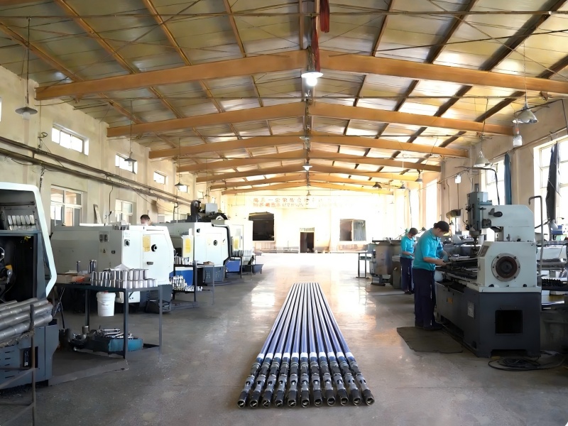
4. Engineering Solution III: Advanced Metallurgy for Abrasive Resistance
Plunger Technology: Instead of traditional Chrome Plating, we recommend custom Ni-based Spray Metal (Nickel-based Alloy). With a hardness of HRC 75-80, the spray metal forms a metallurgical bond with the base metal, preventing the brittle flaking often seen in chrome layers under heavy sand impact. Valve Components: We utilize premium Tungsten Carbide or Silicon Nitride for balls and seats. Every valve set undergoes 100% vacuum leak testing to ensure a tight seal even in fluid containing fine abrasive fines. Barrel Hardening: Using our extra-long CNC Induction Hardening lines, we ensure a uniform ID hardened layer of 0.040" - 0.060", providing a substantial "sacrificial thickness" to withstand long-term abrasion.