

Introduction
Every sucker rod pump put into service begins a countdown. From the moment it starts cycling downhole — typically between 6 and 20 strokes per minute, 24 hours a day — its components are accumulating wear, fatigue, and corrosion damage at rates determined by the well conditions they're operating in. For production engineers and operations teams, understanding which parts wear fastest, why they wear in specific patterns, and what can be done to extend their service life is not academic knowledge. It is the practical foundation of artificial lift cost management.
The economics are significant. When a sucker rod pump fails prematurely, you're not just replacing a pump. You're paying for a workover that can cost anywhere from $30,000 to $100,000+ depending on well depth, location, and rig availability. You're losing production during the workover period. And if the failure mode was predictable and preventable through better component specification, you've paid a completely unnecessary cost.
This guide covers the internal mechanics of sucker rod pump wear in operational depth — which components fail first, the physical mechanisms driving that failure, how different well conditions accelerate specific wear patterns, and what component design and material upgrades are available to change the failure sequence. We've drawn on field experience documented in industry forums, engineering discussions from Reddit's petroleum engineering communities and Quora's oilfield technology threads, and manufacturer-level technical knowledge of how pumps are built to understand how they fail.
The goal is to give you the diagnostic framework and the material knowledge to make better decisions about pump specification, maintenance intervals, and component replacement — decisions that directly affect your artificial lift cost per barrel.
Understanding the Sucker Rod Pump as a Wear System
Before examining individual components, it's worth framing the sucker rod pump as a complete mechanical system under continuous stress. Every component in the pump is subject to some combination of four degradation mechanisms:
Abrasive wear: Physical removal of surface material by harder particles — primarily formation sand — moving across component surfaces under pressure.
Adhesive wear: Material transfer between two surfaces in sliding contact when the lubricating film between them breaks down. In pump barrels and plungers, the produced fluid itself serves as a lubricant — fluid properties (viscosity, lubricity, water content) directly affect adhesive wear rates.
Corrosive wear: Chemical attack of component surfaces by produced fluid constituents — primarily dissolved gases (H₂S, CO₂), formation water (often highly saline), and organic acids sometimes present in crude. Corrosive wear dissolves or weakens material surfaces, making them more susceptible to subsequent abrasive and adhesive mechanisms.
Fatigue failure: Repeated stress cycling — every pump stroke applies compressive and tensile loads to components — eventually initiates and propagates cracks in the material. Fatigue failure is a function of stress amplitude, number of cycles, and material quality.
In a properly specified sucker rod pump operating in clean, moderate conditions, all four mechanisms operate slowly. In poorly specified pumps or standard pumps in harsh conditions, one or more mechanisms accelerate dramatically — driving early component failure.
The Primary Wear Couple: Plunger and Pump Barrel
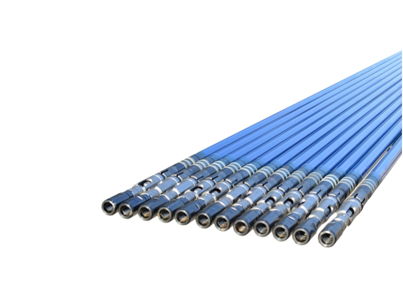
The plunger-to-barrel interface is the highest-consequence wear location in a sucker rod pump. The plunger reciprocates within the pump barrel over every stroke cycle — thousands of cycles per day — while the close-tolerance clearance between them maintains the pressure differential that makes the pump function.
Why the Plunger-Barrel Interface Wears
The plunger surface and barrel bore are in near-contact across the length of the plunger at every moment during operation. The clearance between them — ranging from 0.0005" at the tightest API fit class to 0.0025" at the loosest — is not space. It is filled with produced fluid that serves simultaneously as the pressure seal and the lubricating film preventing direct metal-to-metal contact.
When this fluid film is adequate — clean, lubricating fluid of appropriate viscosity — wear rates at the plunger-barrel interface are low and the pump runs for its designed service life. When the film is disrupted — by sand particles that bridge the clearance, by gas bubbles that create dry contact zones, by corrosive fluid components that attack the metal surfaces — wear accelerates rapidly.
Wear Pattern Analysis: What Failure Looks Like
Uniform barrel wear: When wear is distributed evenly around the bore circumference and along the barrel length, the cause is typically general abrasion from small sand particles or adhesive wear from inadequate fluid lubrication. This pattern progresses gradually — volumetric efficiency declines slowly as the plunger-barrel clearance opens up, the production decline is measurable on a pump card, and the pump typically gives adequate warning before failure.
Localized barrel wear (scoring): Scoring — deep, directional grooves cut into the barrel bore — indicates a specific failure event rather than gradual wear progression. Large sand particles trapped in the clearance, or plunger contact with the barrel wall due to misalignment, create scoring that rapidly renders the sealing surface non-functional. Scoring can cause pump failure within days of occurrence.
Plunger surface wear and coating failure: Chrome-plated plunger surfaces wear through in two stages: first, the chrome deposit thins progressively; then the substrate steel underneath is exposed. Steel-on-steel contact in the barrel accelerates wear dramatically compared to chrome-on-chrome. The transition from chrome wear to substrate exposure is often the functional end of plunger life.
Spray metal plunger performance: Dongsheng's manufacturing capability includes spray metal plunger production — thermal spray coating processes that apply tungsten carbide or chrome carbide cermet coatings to the plunger surface. Spray metal coatings provide substantially harder surfaces than electroplated chrome (often exceeding 1400 HV versus 900-1000 HV for hard chrome), with superior performance in abrasive service. Spray metal plungers used in sand-producing wells routinely achieve run lives 2-3 times longer than chrome-plated alternatives in the same conditions.
The Role of Plunger Fit Class in Wear Rate
API 11AX defines four plunger fit classes based on diametral clearance. Fit class selection directly determines wear rate trajectory:
Too tight a clearance for the fluid viscosity and sand conditions: The clearance is too small for the produced fluid to maintain a consistent lubricating film, or sand particles bridge the gap rather than flowing through. Result: accelerated adhesive wear or scoring.
Correct clearance for the application: The fluid film is maintained consistently, sand particles of reasonable size pass through without bridging, and the pump runs near its design wear rate.
Too loose a clearance for the fluid viscosity: The clearance is so large that the pressure seal leaks excessively, reducing volumetric efficiency and requiring the pump to work harder (more strokes per unit of production), which accelerates overall wear.
The precision with which a manufacturer can hit target fit classes determines how consistently pumps across an order achieve design wear rates. Dongsheng's manufacturing processes include alignment and unified grinding — where the plunger and barrel are ground and measured as a matched pair to achieve target clearance rather than relying on interchangeable-part tolerance stacking. This approach produces tighter clearance control and more consistent wear rates than standard manufacturing methods.
The Second Failure Point: Pump Valves
The traveling valve and standing valve assemblies are the next most common failure locations in sucker rod pumps, and in high-sand or high-abrasion environments, they are sometimes the first to fail.
How Pump Valves Work and Why They Wear
The traveling valve (located in the plunger assembly) and standing valve (located at the bottom of the pump barrel, just above the pump intake) each operate on the same basic principle: a ball lifts off a machined seat to allow fluid flow in one direction, and seats against it to prevent backflow in the opposite direction. The sealing quality of ball-on-seat contact is what maintains the pressure differential between the pump chamber above and below the traveling valve — and between the pump and the tubing above the standing valve.
Every pump stroke involves at least two seating events per valve — the ball impacts the seat at the bottom of the downstroke or upstroke and must seal immediately. At typical pump speeds and well pressures, this represents hundreds of thousands of seating impacts per month. The ball and seat must maintain a precise, leak-free contact geometry through all of these impacts while exposed to the abrasive and corrosive produced fluid.
Valve Wear Mechanisms and Failure Modes
Abrasive wear of ball and seat: Sand particles entrained in the produced fluid are present at both valve locations. When the valve snaps shut, sand particles between the ball and seat abrade both surfaces with every impact. The ball develops flats — planar wear surfaces that prevent complete sealing. The seat develops ring wear — a groove worn into the seating surface that similarly prevents complete sealing. The result is valve leakage that reduces pump volumetric efficiency and eventually renders the pump non-functional.
Impact fatigue failure: At high pump speeds or high differential pressures, valve balls experience significant impact loads on every seating event. Over millions of cycles, this can initiate fatigue cracks in the ball material, particularly if the material quality is at or near the minimum specification. Ball fracture — the ball shattering rather than wearing — is the acute failure mode of impact fatigue, and it is catastrophic. Fractured ball pieces can jam the valve cage, prevent valve opening, or travel uphole to cause additional damage.
Corrosive attack on valve seats: In H₂S-containing or CO₂-saturated produced fluids, valve seat materials can be attacked chemically. Surface pitting from corrosive attack reduces seating contact quality and creates stress concentration sites for fatigue crack initiation. Corrosive attack is particularly damaging on carbon steel seats that lack adequate protective alloying.
Valve cage and traveling assembly wear: The valve cage that contains the ball and guides its motion is also a wear surface. Sand abrasion of the cage interior reduces the precision of ball guidance, eventually allowing lateral ball movement that misaligns the ball with the seat and prevents clean seating.
Valve Material Selection: The Cost-Effective Upgrade
Of all the component material upgrades available for sucker rod pumps, tungsten carbide valve balls and seats represent one of the best cost-to-run-life ratios available. The hardness differential is extreme: standard 440C stainless steel valve balls run 58-60 HRC; tungsten carbide balls run 89-93 HRA — an order of magnitude harder than the sand particles that would otherwise abrade them.
In wells with sand cut levels that visibly reduce the service life of standard steel valves (typically above 0.5% sand by volume in produced fluid), tungsten carbide valve components typically extend valve service life by 3-5 times compared to steel alternatives. The incremental cost per pump is recovered within the first extended service interval in wells that would otherwise require more frequent workover for valve replacement.
For H₂S-dominant or high-CO₂ environments, Inconel 625 or 17-4 PH stainless steel valve components provide the corrosion resistance that prevents the chemical attack failure mode. Dongsheng's steam injection thermal recovery pump specifically incorporates Inconel 625 alloy in its critical flow path components — the same corrosion and temperature resistance properties that make Inconel 625 appropriate for steam service also make it appropriate for corrosive produced fluid service.
Sand-Induced Failure: The Accelerant That Changes Everything
Sand production from the formation is the single most common accelerant of sucker rod pump wear. Understanding how sand interacts with each pump component — and what design responses are available — is essential for operators in any sand-producing field.
How Sand Reaches and Damages Each Component
Sand enters the sucker rod pump with the produced fluid through the pump intake. From that entry point, it follows the fluid flow path through the standing valve, into the pump barrel, through the traveling valve, and out through the plunger bore into the tubing string above.
Standing valve damage: Sand-laden fluid impacts the standing valve ball and seat on every downstroke. High sand concentrations accelerate ball-seat wear faster at this location than anywhere else in the pump because the flow velocity through the intake is highest here and the sand particle density in the incoming fluid is at its maximum.
Pump barrel abrasion: Sand in the fluid film between plunger and barrel acts as a fine-grit grinding compound across the entire length of plunger travel. Even fine sand (below 100 microns) contributes meaningfully to barrel wear when concentrations are significant. Coarser sand (above 200 microns) can bridge the plunger-barrel clearance, creating scoring events that cause acute failure rather than gradual degradation.
Traveling valve damage: Sand concentration in the pump chamber (above the standing valve, below the traveling valve) is lower than in the incoming fluid — some settling occurs — but is still significant. The traveling valve experiences similar ball-seat wear to the standing valve, typically at a slightly lower rate due to lower flow velocity.
Plunger jamming: When large sand particles accumulate below the plunger during the downstroke, they can hydraulically lock the pump — the plunger cannot complete its stroke because incompressible solids occupy the space it needs to enter. This "sand lock" condition prevents pumping entirely and often requires workover to clear.
The Long Plunger Sand Control Design Response
The long plunger sand control sucker rod pump design addresses the specific mechanics of sand-related plunger-barrel wear. In a standard-length plunger design, sand accumulation at the bottom of the plunger travel can cause the plunger to tilt slightly as it descends — this tilt, even at sub-millimeter scale, creates uneven contact between plunger and barrel that concentrates wear and scoring risk at specific locations.
The long plunger design maintains plunger alignment through a greater bearing length. The extended plunger surface area provides more contact support, reducing tilt sensitivity and distributing contact forces more evenly across the barrel length. In sand-producing wells, long plunger configurations consistently achieve longer run lives than standard-length plunger alternatives operating in the same conditions — the alignment benefit directly reduces the localized scoring events that cause the most acute failures.
As one production engineer described in an oilfield Reddit discussion: "We switched to long plunger sand control designs across our heavy oil program after tracking our workover causes for a year. Ball-seat wear and plunger scoring in sandy wells accounted for over 60% of our workovers. Long plunger design cut that category by more than half."
Gas-Related Failure Mechanisms
Gas — whether free gas in the produced fluid or gas that breaks out of solution under the reduced pressure conditions at pump depth — creates failure mechanisms in sucker rod pumps that are distinct from mechanical abrasion.
Gas Lock: The Complete Failure Mode
Gas lock occurs when free gas accumulates in the pump barrel above the standing valve to the extent that the traveling valve cannot open on the upstroke. The mechanism is counterintuitive to those expecting mechanical failure: the pump isn't breaking — it's operating normally, but the compressibility of gas prevents the pressure differential needed to open the traveling valve from being achieved. The pump strokes without moving fluid, generating no production.
Gas lock does not immediately damage pump components, but the secondary effects are harmful. A pump locked on gas continues to move the sucker rod string under near-zero load — this altered load pattern affects rod string stress distribution and can accelerate sucker rod fatigue. If the pump eventually breaks out of gas lock through random pressure events, the sudden reestablishment of liquid column load on the sucker rods creates transient dynamic loading that can exceed fatigue limits.
Liquid Hammer: The Acute Failure Mode
Liquid hammer — the sudden impact of the traveling valve assembly against the standing valve or pump seat when the pump cycles from a gas-locked condition to full fluid contact — is the most damaging acute failure mode associated with gas production. The impact loads involved can fracture valve cages, distort valve seats, damage plunger assemblies, and crack pump barrels. Liquid hammer events have also been responsible for sucker rod failures and surface equipment damage transmitted through the rod string.
The Anti-Gas Sucker Rod Pump Design Response
Dongsheng's anti-gas sucker rod pump addresses gas-related failure through mechanical redesign of the inlet valve system. The key innovation is a mechanical open-and-close oil inlet valve structure that uses the reciprocating motion of the pump rod — rather than fluid pressure differential alone — to drive valve opening and closing. This mechanical actuation prevents gas accumulation in the pump cavity by ensuring the inlet valve opens on every downstroke regardless of gas pressure conditions.
The anti-gas design incorporates three specific engineering features that address the failure mechanisms described above:
Mechanical valve actuation: The pump rod directly drives inlet valve motion, preventing the gas accumulation that enables gas lock to develop. Gas that enters the pump cavity is forced out through the discharge path rather than accumulating.
High-strength corrosion-resistant alloy inlet valve materials: Because the mechanically actuated inlet valve operates under different dynamic loading than a pressure-differential-only valve, its components are specified in corrosion-resistant alloy rather than standard carbon steel. This prevents material fatigue failure from the repeated mechanical actuation that gas-handling service demands.
Streamlined guide channel geometry: The fluid flow path through the pump is optimized to minimize turbulence and pressure recovery. Reduced turbulence lowers the local pressure drops within the pump that accelerate dissolved gas breakout from crude oil — keeping gas in solution through more of the pump path reduces the gas volume available to cause locking.
These three features together systematically prevent the failure modes that gas lock and liquid hammer cause — not by tolerating them but by eliminating the conditions that produce them.
Temperature and Thermal Cycling Effects on Pump Wear
Well temperature — and particularly thermal cycling in wells that undergo steam injection and production cycles — creates wear mechanisms that standard pump designs are not built to handle.
Thermal Expansion Effects on Clearance
Pump components expand with temperature. The plunger-barrel clearance specified at ambient conditions changes when both components are at downhole temperature — the change is typically small in moderate-temperature wells but becomes significant in high-temperature applications.
More importantly, differential thermal expansion between dissimilar materials in the pump assembly can create stress concentrations and dimensional changes that alter component fit. Chrome plating on steel barrels and plungers has a different thermal expansion coefficient than the substrate steel — at elevated temperatures, this differential can cause chrome layer stress and, over many thermal cycles, coating delamination.
Steam Injection Thermal Recovery: Extreme Thermal Challenge
The steam injection thermal recovery environment creates pump component challenges that standard pump designs cannot survive. When steam at 300-350°C is injected through or around the pump — to reduce heavy crude viscosity for production — every wetted component in the steam flow path is exposed to sustained high-temperature, high-pressure steam scouring.
Standard steel components soften and lose dimensional stability. Standard chrome platings fail under thermal cycling stress. Standard sealing mechanisms cannot maintain integrity through repeated heating and cooling cycles.
Dongsheng's steam injection thermal recovery single use syringe pump is purpose-built for this environment. The critical design elements that address thermal failure mechanisms include:
Inconel 625 alloy channeling: The steam flow path through the pump uses Inconel 625 alloy bushings. Inconel 625 is a nickel-chromium-molybdenum superalloy that maintains its strength and corrosion resistance at temperatures exceeding 980°C — far beyond the 350°C operating temperature of steam injection applications. This material selection directly prevents the softening, distortion, and chemical attack that cause standard alloy components to fail under continuous steam scouring.
±0.01mm tolerance cone surface sealing: The plunger cone surface that seals against the pump barrel during the production phase must achieve metal-to-metal sealing after every thermal recovery cycle. Maintaining the dimensional precision necessary for 15MPa metal seal integrity through repeated thermal cycling requires machining tolerances of ±0.01mm — tolerance levels that require precision CNC machining and rigorous measurement. This dimensional precision was validated in field testing at Liaohe Oilfield, where the pump maintained ≥85% steam dryness retention across multiple thermal recovery cycles.
Mechanical linkage integration: The 200mm sucker rod lift that activates steam injection mode — connecting the steam channel to the tubing string through the sealing tube mechanism — must operate reliably after extended service in high-temperature conditions. The mechanical linkage components that achieve this function are specified and tested for thermal stability across the expected service temperature range.
The On-Off Tool: A Component That Fails Silently
The on-off tool — the mechanism that connects the sucker rod string to the pump and allows the two to be separated without pulling the pump — is a component whose failure often goes unrecognized until it causes operational problems.
How the On-Off Tool Fails
The on-off tool engagement mechanism undergoes repeated make-up and break-out cycles. Each cycle applies torque and axial force to the engagement surfaces. Over time:
Engagement surface wear: The engagement faces that transmit torque between the rod string and the pump wear with each make-up and break-out. Worn engagement surfaces require higher engagement torque to achieve reliable connection — and can fail to transmit full rod string torque, causing slippage during pump operation.
Corrosion of engagement mechanisms: In the downhole environment, on-off tool mechanisms are exposed to produced fluid. Corrosion of engagement surfaces reduces the precision of the engagement geometry, further reducing reliable torque transmission.
Fatigue failure of high-stress sections: The on-off tool cross-section changes create stress concentration points. Under repeated cyclic loading from pump operation, fatigue cracks can initiate at these locations.
Dongsheng's on-off tool design addresses these failure mechanisms directly: key areas use thicker material cross-sections and surface hardening to achieve excellent strength; the design specification includes engineered fatigue resistance, corrosion resistance, and wear resistance; and the engagement mechanism is designed for field simplicity — enabling workers to separate the rod column from the pump without stripping while leaving the pump downhole.
Recognizing On-Off Tool Wear Before Failure
On-off tool wear is often diagnosable before failure through surface indicators:
Increasing engagement torque required during rod string make-up operations
Visible wear marks on engagement surfaces during routine rod string inspections
Changes in pump dynamometer card shape that suggest altered rod-to-pump force transmission
Catching on-off tool wear at this stage — and replacing the tool before failure — avoids the more expensive failure scenario where the rod string separates from the pump downhole, requiring a fishing operation rather than a routine rod string pull.
Wear Progression in the Pump Barrel: A Timeline Perspective
Understanding how barrel wear progresses through a pump's service life helps engineers set appropriate inspection intervals and replacement criteria.
Stage 1: Run-In Wear (0-30 Days)
New pump components have surface asperities — microscopic high spots from machining — that wear rapidly in the first operating period. This "break-in" wear is normal. Run-in wear rate is higher than steady-state wear and should not be extrapolated to predict long-term run life.
During run-in, it's important that the pump is not operated under stress conditions — extremely high pump speeds, abnormally high fluid temperatures, or unusually high sand concentrations during this period can cause run-in wear to transition into damage rather than the normal surface conforming that should occur.
Stage 2: Steady-State Wear (The Design Service Life)
After run-in, wear rate settles into a lower, more stable regime. Volumetric efficiency is at or near its design value. The pump is generating the production rate it was specified for. This period represents the value delivery phase of the pump's service life.
The duration of this phase — the actual "run life" that operators are trying to maximize — is the product of:
The quality and hardness of the barrel bore surface
The quality and hardness of the plunger surface coating
The clarity (sand content) and lubricity of the produced fluid
The plunger-barrel clearance (fit class) appropriate to the fluid and conditions
The pump's operating speed (strokes per minute — lower speeds mean lower wear rate per unit time)
A thread on Reddit's r/PetroleumEngineering captured the operational reality: "Run life in our sand-prone heavy oil wells went from an average of 8 months to 16 months when we upgraded from standard chrome barrel and plunger to chrome barrel with spray metal plunger. That's a 50% reduction in workover frequency across a 40-well program — the cost math is not even close."
Stage 3: Accelerating Wear (End of Life Approach)
As the barrel and plunger surfaces wear, the clearance increases beyond the original fit class specification. Several effects compound:
Volumetric efficiency declines as leakage past the plunger-barrel clearance increases
The reduced fluid film quality in the enlarged clearance accelerates wear further (a self-amplifying process)
Surface coating thinness increases susceptibility to breakthrough failures
In this stage, pump dynamometer cards begin showing characteristic changes: reduced fluid load per stroke, changed load distribution patterns, and sometimes erratic behavior from intermittent fluid pounding.
Identifying the Right Replacement Threshold
The decision point for pump replacement — before catastrophic failure requiring emergency workover versus planned workover at a convenient scheduled time — is one of the highest-value decisions in artificial lift management.
Tools for identifying an approach to end-of-life include:
Pump dynamometer card analysis: Changes in card shape and fluid level behavior reveal declining volumetric efficiency
Fluid pound detection: Fluid pound signatures on the dynamometer card indicate the pump is not filling completely, suggesting declining pump efficiency
Production trend analysis: Consistent decline in pump-attributed production against a stable drawdown calculation suggests pump efficiency decline rather than a reservoir decline
Establishing baseline dynamometer card characteristics at initial pump installation — and tracking changes over the pump's service life — provides the data foundation for proactive replacement scheduling.
Material Upgrade Decisions: The Cost-Benefit Framework
For production engineers and procurement managers evaluating component material upgrades, the decision framework is straightforward in principle but requires well-specific data to execute accurately.
The Run Life vs. Upgrade Cost Calculation
For any component material upgrade:
Calculate the cost per workover: This is the complete workover cost — rig, crew, chemicals, wellsite preparation, and lost production during the workover period. This is the cost you're trying to avoid with extended run life.
Estimate the current run life: Based on historical workover data for the well or similar wells in the field.
Estimate the expected run life improvement: This comes from field data on comparable material upgrades in similar well conditions. For tungsten carbide valves vs. steel in sand-producing wells, documented 3-5x run life improvement is consistent across multiple field studies. For spray metal plungers vs. chrome-plated plungers in abrasive service, a 2-4x improvement is well documented.
Calculate the upgrade cost per pump: The incremental cost of the upgraded component specification.
Calculate the break-even: At what run-life multiple does the upgrade cost exactly equal the workover cost savings?
In the vast majority of cases, this calculation strongly favors material upgrades for wells with any significant abrasive or corrosive service conditions. The economics are rarely close — the upgrade cost is typically a small fraction of even one avoided workover.
Component Upgrade Priority Guide
Based on failure frequency data across diverse operating conditions:
Highest priority — Valve components (balls and seats): Tungsten carbide balls and seats in any well with sand cut above 0.5%. Corrosion-resistant alloy (17-4 PH, Inconel 625) in any well with H₂S above 10 ppm or CO₂ above 3%. These upgrades affect the components that fail first most frequently, at the lowest incremental cost.
High priority — Plunger surface coating: Spray metal plunger in any well with consistent sand production or heavy crude (above 500 cP at pump depth). The plunger is the second most frequent first-failure component, and the surface coating is the primary determinant of abrasive wear resistance.
Medium priority — Barrel surface treatment: Chrome-plated barrel in all sand-producing wells (standard API minimums should not be considered adequate where any meaningful sand is produced). Nitrided barrel for applications with fatigue loading concerns.
Situation-specific — Complete specialty pump design: For wells with severe gas production, long plunger sand control design. For thermal recovery operations, a purpose-built steam injection thermal recovery pump with Inconel 625 internals. For high-GOR wells, anti-gas pump design with mechanical valve actuation.
Recognizing Wear From Surface Indicators
Production engineers and well operators don't always have access to the pump for direct inspection. Surface-observable indicators provide important wear signals.
Dynamometer Card Signatures of Component Wear
The pump dynamometer card — a plot of rod load vs. position through the pump stroke — contains diagnostic information about specific component failures when analyzed correctly.
Valve leak signature: A characteristic "parallelogram" distortion of the downstroke portion of the dynamometer card indicates the traveling valve is leaking. Fluid loaded on the upstroke is leaking back through the traveling valve on the downstroke rather than lifting to surface. The magnitude of the distortion correlates approximately with the severity of the leak.
Standing valve leak signature: Similar distortion affecting the upstroke portion of the card. The standing valve is not holding the fluid column above it during the upstroke — fluid is leaking back through the standing valve as the plunger rises.
Fluid pound signature: The characteristic "spike" at the bottom of the dynamometer card downstroke indicates the plunger is impacting fluid suddenly after traveling through a gas-filled space. This signal indicates either gas accumulation in the pump (approaching gas lock) or pump-off conditions (the well is not producing enough fluid to fill the pump on every stroke).
Plunger-barrel wear signature: Reduced fluid load per stroke — visible as a compressed vertical scale on the dynamometer card compared to initial installation baseline — indicates increasing plunger-barrel clearance and declining volumetric efficiency.
Production Decline Attributed to Pump vs. Reservoir
Distinguishing pump wear-induced production decline from natural reservoir pressure decline is important for prioritizing workovers. Indicators that the decline is pump-related rather than reservoir-related:
Decline began abruptly or accelerated significantly at a specific point in time (often indicating a specific failure event) rather than following a smooth exponential decline
Pump dynamometer card shows efficiency loss indicators (valve leakage, fluid pound) consistent with declining performance
Inflow performance relationship (IPR) analysis suggests the reservoir has more deliverability than the pump is extracting
Similar wells on comparable reservoir blocks are maintaining production without comparable decline
Conclusion
Understanding what wears first in a sucker rod pump — and why — transforms maintenance and procurement decisions from reactive to proactive. The plunger-barrel interface and valve assemblies are the primary wear locations in standard well conditions. In sand-producing wells, valves often lead the failure sequence. In high-GOR wells, gas lock and liquid hammer create failure modes that bypass normal wear progression entirely. In thermal recovery operations, temperature determines component survival before mechanical wear becomes relevant.
For each of these failure modes, engineering responses exist that shift the failure sequence — longer run lives, more predictable performance decline, and reduced unplanned workover frequency. Tungsten carbide valves, spray metal plungers, long plunger sand control designs, mechanical anti-gas valve systems, and high-temperature alloy components for thermal service are not premium product upsells. They are engineering solutions to specific, documented failure mechanisms that have well-characterized cost justifications when evaluated against the workover costs they displace.
The sucker rod pump programs with the lowest artificial lift costs per barrel are not the ones that buy the cheapest pumps. They are the ones that match pump specifications to well conditions accurately, select component materials that resist the dominant failure mechanism in each well category, and track performance data closely enough to replace pumps proactively rather than reactively.
Get the specification right — starting with the well data that drives it — and every other cost metric follows from that foundation.
FAQ
Q: How long do sucker rod pump valves typically last compared to the pump barrel and plunger?
A: In clean, low-sand well conditions, standard steel valve balls and seats often outlast the plunger-barrel wear couple — meaning the barrel and plunger will be replaced first. However, in sand-producing wells (sand cut above 0.5% by volume), valve wear frequently outpaces barrel and plunger wear, making valves the first component to require replacement or causing the first operational failure. The relationship inverts based on well conditions. For wells with any meaningful sand production, specifying tungsten carbide valve balls and seats at initial pump installation is almost always cost-justified — the incremental cost per pump is small relative to a single valve-related workover. Tieling Dongsheng's pump configurations are available with tungsten carbide valve components as a standard upgrade option, supported by their 24+ years of experience serving China's sand-producing oilfields.
Q: What are the signs that a sucker rod pump plunger needs replacement before running a workover?
A: The most reliable surface indicator is the pump dynamometer card. A declining fluid load per stroke — visible as a reduction in the vertical height of the dynamometer card compared to baseline — indicates increasing plunger-barrel clearance and declining volumetric efficiency. Supporting indicators include declining pump-attributed production against a stable inflow performance, increased pump-off frequency (the well can't keep up with pump displacement because efficiency is low), and valve leak signatures on the dynamometer card (the reduced pressure differential from plunger-barrel leakage can affect valve operation). When these indicators appear consistently and worsen over a 2-4 week observation period, proactive workover scheduling — rather than waiting for complete pump failure — typically reduces total operational disruption by avoiding emergency rig mobilization and allowing the workover to be scheduled for optimal operational timing.
Q: Why does sand cause pump failure faster than other well conditions?
A: Sand accelerates pump wear through multiple simultaneous mechanisms that compound each other. Abrasive sand particles in the plunger-barrel clearance act as a grinding compound against both surfaces, accelerating material removal compared to clean fluid operation. Sand particles impacting valve balls and seats with every valve closure event wear away the seating geometry that maintains pump pressure. Sand accumulation below the plunger can cause scoring events — acute failure rather than gradual wear — when coarse particles bridge the clearance and create metal-to-metal contact. And sand accumulation in the pump sump can cause sand lock — a physical block preventing plunger travel — that can mechanically damage the pump and rod string through impact loading. Dongsheng's long plunger sand control pump design addresses the alignment and plunger-barrel wear aspects of sand failure, while tungsten carbide valve components address the valve wear aspect. For wells with high sand production, both design features together provide the most comprehensive protection.