

A comprehensive technical reference for petroleum engineers, procurement specialists, and oilfield operators — covering pump selection, material specifications, common field failures, and purchasing best practices.
Introduction
If you have ever stood at a well site watching a beam pump nod rhythmically against the horizon and wondered exactly what is happening three thousand feet below ground, the answer begins with a Sucker Rod Pump — one of the most reliable, widely deployed pieces of equipment in the entire history of oil production.
Roughly 80 percent of the world's artificially lifted oil wells depend on rod lift systems. At the heart of every one of them is the subsurface pump — the component that actually moves fluid from the producing formation to the surface. And since the mid-20th century, the design, dimensional tolerances, material requirements, and testing procedures for that pump have been codified by a single document: API Specification 11AX, Specification for Subsurface Sucker Rod Pump Assemblies, Components, and Fittings.
The market is crowded. You can find subsurface pumps offered at wildly different price points, from verified API-licensed manufacturers to uncertified knockoffs that look identical in a catalog photo but fail within weeks downhole. The cost of a pulled pump — rig time, deferred production, workover expenses — dwarfs the price difference between a quality unit and a cheap substitute. An operator running 200 wells who saves $400 per pump at purchase but loses an average of two extra workover days per pull is almost certainly losing money on that decision.
This buyer's guide exists to close that knowledge gap. Whether you are specifying a pump for a new completion, troubleshooting high run-time failures on existing wells, or qualifying a new vendor, the following pages walk you through every decision point: pump type, bore selection, clearance, metallurgy, designation code, common mistakes, and the questions you should always ask a supplier before issuing a purchase order.
The goal is not to make you an expert pump designer — it is to make you an informed buyer who cannot be sold the wrong thing.
What Is a Sucker Rod Pump?
A Sucker Rod Pump is a positive-displacement, reciprocating downhole pump that lifts reservoir fluid to the surface by converting the linear motion of a steel rod string into pumping action. The system is mechanically simple: a surface pumping unit — the iconic "nodding donkey" or beam pump — drives a polished rod up and down, and that motion is transmitted to the subsurface pump through a continuous string of threaded steel sucker rods.
The pump itself consists of four fundamental components:
Barrel — the cylindrical chamber in which fluid is displaced
Plunger — the precision-fitted piston that reciprocates inside the barrel
Standing Valve — a check valve at the bottom of the pump that allows fluid in but prevents backflow
Traveling Valve — a check valve on the plunger that opens on the upstroke to lift fluid above it
The Pumping Cycle Explained
On the upstroke, the rod string pulls the plunger upward. The pressure drop below the plunger opens the standing valve, drawing formation fluid into the barrel from the tubing. Meanwhile, the fluid already sitting above the traveling valve is lifted toward the surface. On the downstroke, the plunger descends, the standing valve closes (preventing the fluid from being pushed back into the formation), and the traveling valve opens, allowing fluid to pass through the plunger in preparation for the next upstroke. The cycle repeats — typically 4 to 20 times per minute — gradually lifting fluid column by column to surface.
It is worth appreciating just how demanding this service is. A pump set at 6,000 feet operating at 8 strokes per minute executes nearly 4.2 million full cycles per year. Every cycle subjects the plunger and barrel to contact stress, friction, potential abrasion from sand, and chemical attack from corrosive gases. Pump design and material selection are therefore not academic exercises — they are the primary levers that determine whether a pump runs 18 months or 3.
Where Sucker Rod Pumping Fits in Artificial Lift
Sucker rod pumping is the dominant artificial lift method globally because it is cost-effective, mechanically robust, and well understood. It works best for wells producing moderate to low fluid volumes (generally up to ~2,000 BPD), at depths from a few hundred to over 15,000 feet, and across a wide range of fluid gravities. Where it struggles — very high volume, very high GOR, highly deviated wellbores, or extreme depths — operators may turn to electric submersible pumps (ESPs) or gas lift. But for the overwhelming majority of the world's production wells, particularly in mature fields, the Sucker Rod Pump remains the workhorse of choice.
The API 11AX Standard: Why It Exists and What It Covers
Before API Spec 11AX existed, oil producers faced an interoperability nightmare. Pumps from different manufacturers had incompatible dimensions, making spare parts, barrel-plunger replacement, and seating assembly interchange nearly impossible in the field. Downtime from non-fitting components was a chronic operational cost that the industry collectively decided to solve through standardization.
First published in the 1940s and now in its 13th edition (May 2015), API Spec 11AX establishes standardized:
Nominal bore sizes — from 1-1/16 in (27.0 mm) through 3-3/4 in (95.25 mm)
Dimensional tolerances for barrels, plungers, valves, and seating assemblies
Material requirements — minimum hardness, alloy designations, corrosion resistance classes
Test procedures — hydrostatic test pressures, leakage acceptance criteria, valve performance
Marking and identification requirements for traceability
Designation nomenclature — a standardized code that encodes pump type, size, and configuration
Any manufacturer who claims API 11AX compliance must be licensed by the American Petroleum Institute and submit to regular third-party facility audits. The API monogram on a pump is not marketing language — it is a documented, audited claim that the product was manufactured in a facility that meets API's quality system requirements.
Buyer Beware: A catalog listing "API 11AX standard" or "manufactured to API 11AX" does not mean the same thing as holding an active API 11AX monogram license. Always verify the manufacturer's current license status on the official API monogram database before purchasing. An expired or fraudulent license is not uncommon among low-cost suppliers.
Related Standards Every Buyer Should Know
| Standard | Scope |
|---|---|
| API Spec 11AX | Subsurface sucker rod pumps — design, materials, testing, dimensions |
| API RP 11L | Pumping system design — rod string selection, surface unit sizing |
| API RP 11AR | Care and use of subsurface sucker rod pumps — installation, operation |
| NACE MR0175 / ISO 15156 | Material requirements for H₂S (sour) service environments |
| API TR 11L5 | Sucker rod pumping system design methodology reference |
Pump Type Classification: Choosing the Right Architecture
The most consequential decision in any pump specification is the basic type: tubing pump or insert (rod) pump. Each has architectural implications that cascade through every other design choice.
Tubing Pump (API Type: T)
In a tubing pump, the pump barrel is threaded directly into the tubing string as part of the permanent downhole completion. Only the plunger and valve assembly travel with the rod string. The practical consequence: you can retrieve the plunger on the rod string for inspection or replacement without pulling the tubing, but if the barrel itself fails or wears, you must pull the entire tubing string — an expensive workover.
Advantage: Because the barrel is housed inside the tubing ID, the pump bore can be maximized for a given casing size. A 3-1/2-in tubing string can accommodate up to a 2-1/2-in bore tubing pump, whereas the largest insert pump fitting that same tubing string is typically 2-1/16 in. That additional bore diameter translates directly to higher volumetric displacement per stroke — sometimes 30–50% more. Tubing pumps are therefore the preferred choice in high-volume, shallow wells where frequent barrel pull is not expected.
Disadvantage: Barrel maintenance or replacement requires a full tubing pull. In wells with heavy paraffin, scale, or corrosion-accelerated barrel wear, this can be a significant operating cost disadvantage relative to insert pumps.
Insert Pump (API Types: RH, RW, RWA, RHA)
An insert pump — also called a rod pump — is a self-contained assembly (barrel + plunger + valves) that is run into the well on the rod string and latches into a seating nipple previously installed in the tubing. To retrieve the pump, you simply pick up the rod string. No tubing pull is required. This makes insert pumps the overwhelming choice in wells where frequent pump changes are expected or where minimizing workover costs is critical.
| API Type | Full Name | Key Characteristic |
|---|---|---|
| RH | Rod, Heavy Wall | Thick barrel wall — maximum resistance to abrasion and collapse; preferred in sand-laden or corrosive wells |
| RW | Rod, Thin Wall | Standard (thin) wall barrel — lighter, lower cost; most common general-service insert pump |
| RWA | Rod, Thin Wall, Anchor | Thin wall with pull-tube anchor; barrel anchored at both top and bottom for deviated wells |
| RHA | Rod, Heavy Wall, Anchor | Heavy wall with anchor; maximum durability in deviated or abrasive service |
Barrel and Plunger Configuration Options
Beyond the basic type, API 11AX defines several barrel design variants that address specific production challenges:
Soft-Packed Plunger: Replaces the close-clearance metal-to-metal fit with elastomeric packing rings on the plunger. Dramatically reduces gas interference in high-GOR wells by providing a positive seal even when gas migrates above the standing valve. The trade-off is higher friction loads and packing wear.
Double-Barrel (Tandem Barrel): Two barrels connected in series — improves volumetric efficiency by reducing pump-off losses, useful in wells with unstable fluid levels.
Long-Plunger Design: A plunger significantly longer than the barrel stroke, providing more wear surface and maintaining better alignment in deviated wellbores. This is the recommended approach for wells deviating beyond 45 degrees.
Real-World Field Pain Points: What Actually Goes Wrong
Discussions across petroleum engineering forums and oilfield operator communities consistently reveal that most pump failures are not random mechanical events — they are predictable consequences of mismatched pump selection, incorrect sizing, or ignored fluid conditions. Understanding these failure modes before you order is the most cost-effective engineering work you can do.
Gas Lock: The Most Common Field Complaint
Gas lock occurs when free gas accumulates in the pump barrel above the standing valve, compressing and expanding without displacing meaningful fluid. The pump "runs dry" even though fluid is present in the annulus. Operators see the pumping unit stroking normally but surface production falls to near zero.
In high-GOR wells — particularly coalbed methane producers, solution-gas drive reservoirs in late life, or wells near bubble point — gas lock is not a rare event; it is a chronic operational reality. The fix is almost never "pump harder." The correct engineering responses include: setting the pump deeper below the producing interval, installing a properly designed gas anchor upstream of the standing valve, using a pump with a traveling valve vented bleed port, or switching to a soft-packed plunger that provides positive sealing even when gas is present.
Engineers on oilfield forums frequently note that operators who have not experienced gas lock in a new high-GOR field often misdiagnose the condition as pump failure and order a replacement pump — only to have the new pump exhibit the same behavior within days of installation. Gas lock is a system problem, not a pump defect.
Sand and Abrasive Wear
Producing sands are the most common cause of accelerated barrel and plunger wear. A 0.001-in clearance fit between plunger and barrel — designed to minimize leakage — becomes a precision grinding surface when abrasive particles are present. Fine silica sand (50–150 microns) is particularly damaging because it passes easily through most upstream sand control systems but is exactly the right size to become trapped in the plunger-barrel annulus.
The appropriate engineering response is to specify heavier barrel walls (RH type), tungsten carbide-coated plungers, and in severe cases, chrome carbide or ceramic ball and seat assemblies. Larger plunger-barrel clearance (0.003–0.005 in, sometimes called "loose fit") is sometimes used in sand-heavy wells on the theory that sand passes through rather than jamming — but this trade-off reduces volumetric efficiency and must be modeled against production targets.
Corrosion: H₂S, CO₂, and High Water Cut
Sour wells (H₂S present), high-CO₂ environments, and wells with high water cut (BSW above 70%) create aggressive electrochemical environments that attack carbon steel rapidly. Pitting corrosion on barrel inner walls creates a rough surface that accelerates plunger wear; stress corrosion cracking (SCC) in H₂S service can cause sudden brittle fracture of components that appear undamaged externally.
For sour service, NACE MR0175 / ISO 15156 material requirements apply. This mandates specific alloy grades, hardness limits, and heat treatment protocols for all metallic components exposed to the wellbore fluid. A pump that is not built to NACE requirements in an H₂S environment is not a cheaper option — it is a liability waiting to manifest as an expensive failure.
Pump-Off and Fluid Pound
When reservoir inflow is slower than the pump's displacement capacity, the fluid level in the annulus drops below the pump intake. The pump begins "pumping off" — stroking against insufficient fluid. On the downstroke, the plunger impacts the fluid surface with a sudden shock load — this is "fluid pound," and it is audible at surface as a metallic banging.
Sustained fluid pound accelerates rod coupling fatigue, stresses the pumping unit gearbox, and can cause rod string failure over time. The solution is never to simply slow the pump to zero — it is to install a pump-off controller (POC) that detects the dynamometer card signature of fluid pound and automatically reduces stroke rate or introduces rest periods, protecting equipment without sacrificing production from the well's natural inflow capability.
Scale and Paraffin Deposition
In carbonate reservoirs and produced-water environments, calcium carbonate scale can deposit inside the pump barrel, progressively reducing clearance until the plunger seizes. Paraffin precipitation — common in waxy crude wells at temperatures near the cloud point — has the same effect. Neither condition is detectable from surface instrumentation until production declines sharply. Chemical treatment programs (scale inhibitor or paraffin dispersant injection) and regular well testing are the appropriate preventive measures; these must be considered as part of the total lifting system design, not afterthoughts.
Key Selection Criteria: A Systematic Approach to Pump Specification
Experienced artificial lift engineers use a structured decision framework when specifying a downhole pump. The following criteria must be evaluated in sequence — skipping any one can invalidate the entire design.
01. Target Production Rate (BPD)
Begin with the well's expected production rate in barrels per day (BPD). This is determined by inflow performance analysis (IPR curve) at the proposed pump setting depth. The pump must be sized to achieve this rate at an acceptable stroke-per-minute speed — typically 6–12 SPM for most wells. Oversizing the pump creates fluid pound; undersizing leaves production on the table and forces excessive stroke rates that accelerate mechanical wear.
A commonly overlooked point: size for the expected peak production rate over the next 18–24 months, accounting for expected changes in water cut, GOR, and reservoir pressure decline — not solely for today's test separator reading. This typically means selecting one bore size larger than the minimum required.
02. Casing and Tubing Size
The maximum allowable pump bore is constrained by the tubing ID (for insert pumps) or the casing ID (for tubing pumps). The table below provides practical bore limits for common tubing and casing combinations:
| Casing OD | Tubing OD | Max Insert Bore | Max Tubing Pump Bore |
|---|---|---|---|
| 4-1/2" | 2-3/8" | 1-1/16" | — |
| 5-1/2" | 2-7/8" | 1-5/8" | 1-1/4" |
| 5-1/2" | 3-1/2" | 2-1/16" | 1-1/2" |
| 7" | 3-1/2" | 2-1/2" | 2-1/2" |
| 7" | 4-1/2" | 2-3/4" | 3" |
| 9-5/8" | 4-1/2" | 3" | 3-3/4" |
03. Pump Setting Depth
Setting depth influences rod string stretch, effective stroke length, rod loading, and the hydrostatic pressure the pump must overcome. Deeper settings require longer, heavier rod strings that impose greater peak polished rod loads and require more precise rod taper design. API RP 11L provides the calculation methodology. As a rule of thumb, deeper wells favor insert pumps over tubing pumps because the ability to retrieve the pump without a tubing pull becomes more economically valuable as workover costs increase with depth.
04. Gas-Oil Ratio (GOR)
GOR is arguably the most impactful fluid property for pump design. At free-gas fractions above approximately 5–10% of pump intake volume, volumetric efficiency begins to decline meaningfully. Above 20–30%, gas interference becomes severe enough to cause intermittent gas lock. The engineering response must be proactive: properly designed gas anchors can separate free gas before it enters the pump, and should be considered standard equipment in any well with a GOR above 200 SCF/bbl.
05. Fluid Gravity, Viscosity, and Water Cut
Heavy oils (below 20° API) may require larger plunger-barrel clearances to prevent the plunger from binding due to viscous drag, especially at low bottom-hole temperatures. High water cuts (above 70% BSW) increase corrosion potential dramatically — water provides the electrolyte for electrochemical attack on steel components. In these conditions, corrosion-resistant barrel finishes (hard chrome, nickel) and inhibitor injection programs are not optional.
06. Sand Content and Well Deviation
Sand-laden wells call for heavy-wall barrels (RH type) and tungsten carbide plungers as a minimum. Deviated wells (inclination above 30°) impose lateral forces on the plunger that accelerate barrel wear on one side — the classic "banana wear" failure mode. For inclinations above 45°, the long-plunger configuration is strongly recommended. API RHA (heavy wall, anchor) provides the most robust solution for combined sand and deviation service.
07. H₂S / CO₂ Service
Any well with H₂S present above the threshold defined in NACE MR0175 requires materials certified to that standard. All component hardness must be controlled (typically ≤22 HRC for carbon and low-alloy steels in contact with the wellbore fluid), and heat treatment documentation must accompany the pump. Specify "NACE MR0175 / ISO 15156 compliance required" explicitly in your purchase specification and demand material test reports (MTRs) at delivery.
Critical Parameters and Calculations: Getting the Numbers Right
Production Rate Estimation
The theoretical gross production from a Sucker Rod Pump is calculated as:
BPD = (0.1166 × D² × S × N × Ev) ÷ 42
D = Plunger diameter (inches)
S = Effective stroke length (inches)
N = Strokes per minute (SPM)
Ev = Volumetric efficiency (typically 0.65–0.92)
Worked example: A 2-in plunger (D = 2), 60-in effective stroke (S = 60), 8 SPM (N = 8), and 80% volumetric efficiency (Ev = 0.80) gives: BPD = (0.1166 × 4 × 60 × 8 × 0.80) ÷ 42 ≈ 107 BPD
Volumetric efficiency (Ev) is rarely 1.0 in practice. Major reductions come from gas interference (the single largest factor in high-GOR wells), fluid leakage past the plunger (proportional to clearance, differential pressure, and fluid viscosity), and pump fillage (reservoir inflow limited). A reasonable working assumption for design is Ev = 0.70–0.85 for standard service wells; H₂S or heavy-oil wells may see 0.60–0.70.
Plunger-Barrel Clearance
Clearance between the plunger OD and barrel ID controls the trade-off between volumetric efficiency (tight clearance = less leakage = higher efficiency) and susceptibility to sand binding and thermal seizure (loose clearance = more tolerant of contaminants and temperature expansion).
| Clearance (per side) | Fit Class | Recommended Service |
|---|---|---|
| 0.0005–0.001" | No. 1 (Tight) | Clean light oil, low temperature, new wells — maximum efficiency |
| 0.001–0.002" | No. 2 (Standard) | General service — most common specification |
| 0.002–0.003" | No. 3 (Loose) | Moderate sand, heavy oil, deviated wells |
| 0.003–0.005" | No. 4 (Extra Loose) | High sand content, extreme temperature, and steam injection wells |
Barrel Length Selection
Barrel length must accommodate the full plunger stroke plus a mechanical overtravel allowance — typically the effective stroke length plus 12–18 inches. The barrel must also be long enough that the bottom of the plunger is always above the standing valve assembly at the top of the upstroke. Undersized barrel length causes the plunger to exit the barrel — a catastrophic failure that destroys both components and requires complete pump replacement.
Rule: Barrel Length ≥ Effective Stroke + Plunger Length + 12 inches overtravel margin.
Stroke Rate (SPM) Limits
Higher SPM means higher production from a given bore size, but it also means higher cyclic rod loading, more surface unit gearbox stress, and faster pump component wear. Industry best practice targets 6–12 SPM for most production wells. Wells running above 16 SPM should be examined critically — either the pump is undersized for the production target, or the surface unit is improperly configured. Running pumps at maximum rated SPM continuously to compensate for undersizing is one of the fastest paths to premature rod string and pump failure.
Material Specifications: Matching Metallurgy to Mission
No aspect of Sucker Rod Pump specification generates more field controversy than material selection. Engineers who have experienced premature failures in corrosive or abrasive service understand viscerally why a 15–20% premium for upgraded metallurgy is among the highest-return investments in oilfield procurement.
Barrel
The barrel inner surface carries most of the wear load. Standard options:
Chrome-plated (hard chrome, 0.003–0.005" thick): Standard for most service conditions; surface hardness 58–65 HRC
Nickel-plated: Superior corrosion resistance in CO₂-dominated environments
Nitrided/case-hardened: Cost-effective for light service; good for clean wells
Bi-metallic sleeve: For extreme abrasion service — a hardened insert barrel liner within a structural outer shell
Plunger
Chrome-over-nickel: Balanced corrosion and wear resistance; general service standard
Tungsten carbide (TC) spray coating: Maximum abrasion resistance — the gold standard for sand service
Ceramic plasma spray: For corrosive + abrasive combined service (H₂S + sand)
Monel: For high H₂S + chloride environments requiring maximum corrosion resistance
Match plunger hardness to barrel hardness to avoid galvanic acceleration and differential wear patterns.
Ball and Seat Valves
Valve components are often under-specified relative to their impact on pump run life:
440-C stainless (chrome steel): Standard service in clean fluids
Tungsten carbide (WC): Sand, abrasives, high-velocity flow — most recommended; often doubles valve service life
Ceramic: H₂S + corrosive + abrasive combined service
Stellite: High temperature + abrasion (thermal EOR wells, steam injection)
Tungsten carbide balls and seats typically add $200–400 per valve set at purchase. In a well producing meaningful sand, chrome steel seats may require replacement every 90 days; tungsten carbide often runs 12–18 months. The arithmetic almost always favors TC.
Structural Components and NACE Compliance
For sour service (H₂S environments), all metallic components must comply with NACE MR0175 / ISO 15156. This includes:
Hardness limits (≤22 HRC for most carbon and low-alloy steels)
Controlled heat treatment protocols
Alloy restrictions to eliminate susceptible microstructures
Full heat number traceability from mill certificate to finished component
Request hardness test certificates and heat treatment records as part of the delivery documentation package. The additional documentation burden on a compliant manufacturer is minimal — and its absence is a clear signal that the supplier has not actually built to NACE requirements.
Reading the API 11AX Designation Code
Every API 11AX-compliant pump carries a standardized designation code that encodes its complete specification. Understanding how to read this code is an essential skill for anyone purchasing, specifying, or troubleshooting pumps.
Example: 20-125RWBC1
| Segment | Value | Meaning |
|---|---|---|
| Bore Size | 20 | "2-0" → 2-inch bore (first digit = whole inches, second = eighths of an inch) |
| Barrel Length | 125 | 125 inches total barrel length (= 10 ft 5 in) |
| Pump Type | R | Rod (insert) pump; T = Tubing pump |
| Wall Thickness | W | Thin wall; H = Heavy wall |
| Barrel Direction | B | Bottom-anchored barrel, pulled from the bottom; T = Top-anchored |
| Plunger/Valve | C | Plunger type and valve configuration per API 11AX table |
| Seating Type | 1 | Bottom cup-type seating; 2 = Top cup; 3 = Mechanical latch |
A bore designation of "25" would mean 2-5/8-inch bore. "30" = 3 inches, "35" = 3-5/8 inches, and so on.
Always confirm the full designation code — including barrel length and seating type — when placing an order. Two pumps with identical bore and type but different barrel lengths or seating assemblies are not interchangeable. A mismatched seating assembly type means the pump will not latch downhole, requiring an immediate and costly pull.
Common Buying Mistakes That Cost Operators Dearly
After reviewing failure case studies and engineer discussions across oilfield communities, seven buying and specification mistakes emerge repeatedly as the dominant causes of premature pump failures and unnecessary workover costs.
Mistake 1: Selecting pump size based on current production only
A pump sized exactly for today's rate has no margin for declining reservoir pressure, increasing water cut, or seasonal SPM adjustments. Size for the expected peak production rate over the next 18–24 months, not today's test separator reading. This typically means selecting one bore size larger than the minimum required.
Mistake 2: Ignoring GOR when selecting plunger-barrel clearance
Engineers often specify standard clearance (No. 2 fit) by default without reviewing GOR data. In high-GOR wells, tight clearance combined with gas interference causes the fluid film between plunger and barrel to break down, leading to metal-to-metal contact and rapid wear. The correct approach for GOR above 300 SCF/bbl is to consider a soft-packed plunger or at minimum a No. 3 clearance fit with a well-designed gas anchor.
Mistake 3: Skipping NACE compliance because H₂S readings seem low
H₂S concentrations can vary significantly between wells in the same field and can increase as reservoir pressure declines. Many operators have experienced stress corrosion cracking failures in pumps specified without NACE compliance because initial H₂S readings were below the threshold. In any field with known sour potential, specifying NACE materials from the outset is far cheaper than a retrofit after a failure.
Mistake 4: Purchasing from unlicensed "API-compatible" suppliers
The proliferation of catalog descriptions using phrases like "API 11AX standard design" from manufacturers who do not hold a current API monogram license is a serious quality risk. Without the audited quality management system that underlies an API license, dimensional tolerances, material certifications, and test documentation may not meet specification. Verify license status directly at api.org before qualifying a new supplier.
Mistake 5: Specifying barrel length too short for the planned stroke
One of the most damaging field errors is running a pump with insufficient barrel length for the configured surface stroke. When the plunger exits the bottom of the barrel on the upstroke, the valves are destroyed and both barrel and plunger are severely damaged. This is entirely preventable by verifying: Barrel Length ≥ Effective Stroke + Plunger Length + 12 inches.
Mistake 6: Defaulting to chrome steel ball-and-seat assemblies in sand service
Chrome steel (440-C) balls and seats are adequate for clean-fluid wells but wear dramatically faster than tungsten carbide in sand-laden fluids. In a well producing 50 lbs/day of sand, chrome steel seats may need replacement every 90 days; tungsten carbide often runs 12–18 months. The math overwhelmingly favors TC in any well with meaningful sand production, despite the higher initial unit cost.
Mistake 7: Failing to request mill test reports (MTRs)
Material test reports document the chemical composition, heat treatment, and hardness testing results for each component lot. Without MTRs, you have no verifiable evidence that the materials meet specification. In any critical application — deep wells, sour service, heavy lifting — MTRs are non-negotiable. A reputable manufacturer will have this documentation organized and ready without hesitation. Inability or reluctance to provide MTRs is a significant red flag.
What to Look for in a Certified Sucker Rod Pump Manufacturer
Selecting a pump manufacturer is not simply a price exercise. The factors that differentiate a reliable long-term supplier from an unreliable one are knowable in advance — if you ask the right questions.
API 11AX Monogram: The Baseline Non-Negotiable
An active API 11AX monogram license means the manufacturer has passed a third-party audit of its quality management system, production processes, measurement and test equipment, and documentation practices. It is the entry-level requirement for a serious subsurface pump supplier, not a differentiator. If a supplier does not hold a current monogram license, it should not be on your approved vendor list for API-specified applications.
Qualified Supplier Status to Major Operators
Qualification as a material supplier to national oil companies such as CNPC and Sinopec, or to international service companies such as Weatherford, requires completing rigorous vendor qualification audits that go substantially beyond the API monogram. These programs evaluate manufacturing capability, quality system documentation, track record of supply performance, and on-site factory inspections. Approval by these organizations provides a level of independent quality assurance that market-facing certifications alone cannot replicate.
Production Scale and Engineering Capability
High production volume — in excess of 20,000 units per year — combined with a dedicated engineering team is a strong proxy for manufacturing consistency. High-volume production requires tight process control; factories producing only a few hundred units per year cannot justify the capital investment in precision grinding, barrel-honing, and in-process hardness testing equipment that quality production demands. Likewise, an engineering team capable of supporting custom specifications — non-standard bore sizes, specialty alloy requests, NACE documentation packages — adds real value over a distributor who simply relabels commodity products.
The Dongsheng Standard
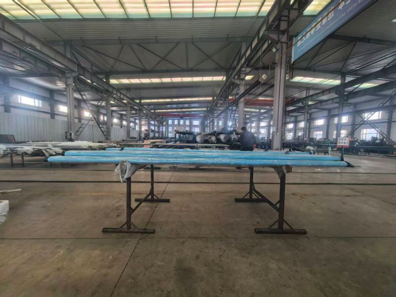
Tieling Dongsheng Petroleum Machinery Co., Ltd. has been manufacturing API-certified subsurface pumps since 2000. With over 25 years of focused experience, the company has built the manufacturing infrastructure, quality systems, and engineering knowledge that serious oilfield procurement requires:
Active API 11AX Monogram — full traceability and third-party audit compliance
ISO 9001 Certified — comprehensive quality management from raw material to final product inspection
ISO 14001 Environmental Management System — meeting international environmental standards
National High-tech Enterprise designation — reflecting ongoing R&D investment and technological capability
Intellectual Property Certifications — proprietary technology development, not commodity replication
CNPC and Sinopec Qualified Supplier — approved by China's two largest national oil companies
Weatherford Qualified Supplier — approved by one of the world's largest oilfield service companies
20,000+ units per year capacity — consistent quality across 100+ product configurations
Global export experience — products deployed in USA, Canada, Romania, Indonesia, and across China's major oilfield basins (Liaohe, Daqing, Changqing, Shengli)
Dongsheng's product line covers the full API 11AX range: standard insert pumps (RH, RW, RWA, RHA), tubing pumps, and a portfolio of specialty products engineered for demanding service conditions — including long-plunger sand control pumps, deep-well pumps with modular barrel design optimized for low-pressure low-liquid-level wells, and heavy-oil insert pumps. Every product passes comprehensive incoming material, in-process, and final inspection before shipment.
Dongsheng's pumps have operated in Liaohe, Daqing, Changqing, and Shengli — four of China's most demanding oilfield environments, spanning heavy oil, deep wells, high-sand production, and high-temperature applications. This field validation across diverse conditions is the most meaningful performance credential a pump manufacturer can present.
Conclusion
The API 11AX Sucker Rod Pump is one of the most extensively standardized pieces of equipment in the oilfield — and yet it remains one of the most frequently misspecified. The gap between a pump that runs 18 months and one that is pulled in 90 days almost always traces back to decisions made before the purchase order was issued: bore selection, clearance fit, material grade, barrel length, and supplier qualification.
Applying the systematic framework in this guide will dramatically reduce the probability of the avoidable failures that account for the majority of premature pump pulls in any active oilfield. Three principles bear emphasis as a closing summary:
1. Understand the fluid before specifying the pump. GOR, H₂S content, sand loading, and water cut each have specific implications for pump type, clearance, and metallurgy that no single default specification can address. A standard No. 2 clearance fit with chrome steel valves is a perfectly good starting point for a clean, low-GOR light oil well — and the wrong choice for a heavy, sandy, sour producer.
2. Treat API 11AX monogram status as the minimum qualification for your supplier — not the differentiator. The differentiator is field-validated performance across diverse operating conditions, engineering support for non-standard requirements, and the documentation integrity to back up every material and dimensional claim. Ask to see MTRs, inspection records, and factory capabilities — not just the certificate.
3. Total cost of ownership is the relevant metric, not purchase price. A pump that runs twice as long on a workovers-intensive well returns far more value than the unit cost differential suggests. When you factor in rig time, deferred production, rod string handling, and crew costs, a premium pump that extends mean time between failures by even 30% typically pays back its cost differential within the first extended run.
Whether you are purchasing your first pump or your ten-thousandth, the discipline of matching pump specification to well conditions — backed by a qualified, audited manufacturer — is the most reliable path to sustainable lifting costs and maximized production uptime.
FAQ
Q1. What is the difference between an API 11AX Rod Pump and a Tubing Pump, and how do I choose?
The fundamental difference is how the pump is retrieved: a rod (insert) pump is run on the rod string and can be pulled without disturbing the tubing, while a tubing pump has its barrel permanently installed in the tubing string and requires a full tubing pull for barrel replacement. Choose an insert pump when you anticipate frequent pump changes due to sand, corrosion, or declining reservoir conditions; when the well is deep and workovers are expensive; or when you need operational flexibility. Choose a tubing pump when maximum bore size — and therefore maximum production capacity — is the primary requirement for a given casing size, and when you expect infrequent pump maintenance because the fluid environment is clean and benign.
Q2. How do I know what plunger-barrel clearance to specify?
Clearance selection balances volumetric efficiency against tolerance of well conditions. For clean, light oil wells with no meaningful sand production and low GOR, specify a No. 1 or No. 2 (tight) fit for maximum efficiency. For wells with sand (even intermittent), heavy oil, high deviation, or elevated temperature, specify No. 3 or No. 4 (loose) fit to prevent sand bridging and thermal seizure. When in doubt, the industry default is No. 2 (0.001–0.002 in per side) for standard service. Always review your water analysis, sand sample data, and GOR before accepting any default specification.
Q3. When is it necessary to specify NACE MR0175 compliance?
NACE MR0175 / ISO 15156 applies whenever the partial pressure of H₂S in the wellbore gas phase exceeds 0.05 psia (0.34 kPa) — a threshold that corresponds to very low H₂S concentrations in most reservoir conditions. In practice, for any well where sour gas is known or suspected to be present, specifying NACE compliance eliminates the risk of sulfide stress cracking (SSC) failure in high-strength steel components. The cost premium for NACE-compliant materials is typically 10–20% and is almost always justified by the consequence avoidance. Request material test reports with hardness readings and heat treatment certifications at delivery.
Q4. How long should a properly specified Sucker Rod Pump last?
In clean-service wells — low sand, low corrosion, stable fluid level, appropriate SPM — a properly specified and installed API 11AX pump routinely achieves 18–36 months run life before requiring inspection or replacement. In aggressive service (sand, H₂S, high water cut, deviation), 9–18 months is a more realistic target, and some applications require 6-month replacement cycles regardless of material upgrades. Tracking your mean time between failures (MTBF) by well category and correlating failures to fluid condition changes is the most reliable diagnostic tool for improving pump run life across your operation.